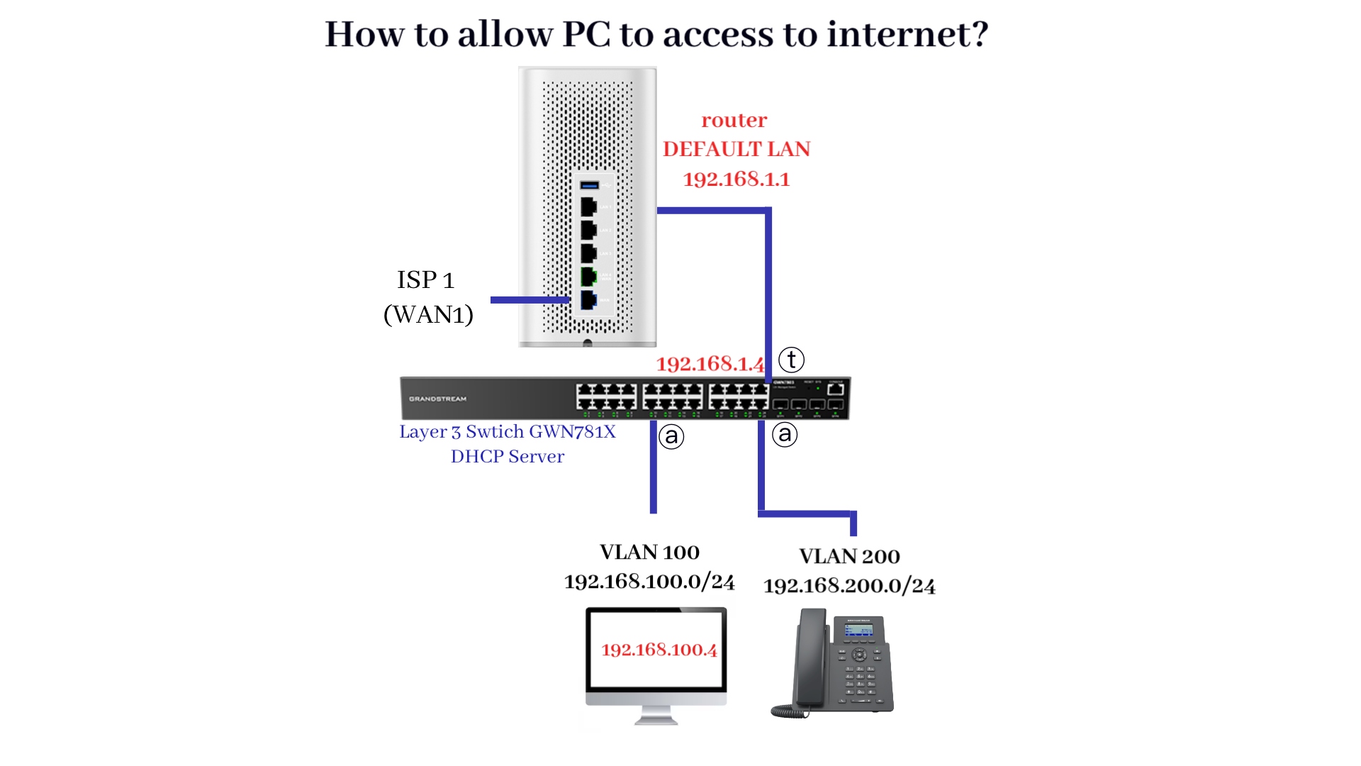
VLANs require a router or Layer 3 device for inter-VLAN communication, while a Layer 3 switch can perform routing between VLANs internally, eliminating the need for an external router. This guide describes the steps on how to create static routes in Grandstream Wi-Fi router GWN7062 and Layer 3 managed network switch GWN781x series. In this example, GWN781X acts as a DHCP server.
Steps
At the switch
① Create VLAN IP Interfaces
② Enable DHCP service
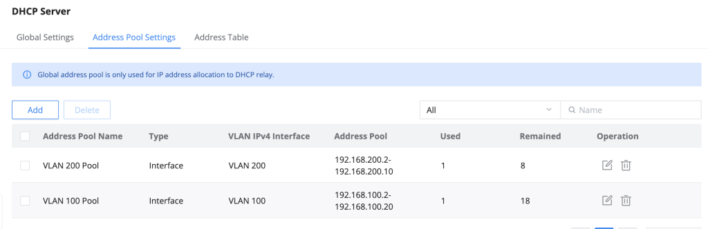
③ Define Address Pool
④ Create VLANs and define the port type (trunk and access)
⑤ Create static routes (destination IP 0.0.0.0/0) to the router
At the router
⑥ Create static routes to each VLAN in the router
How to
① Create VLAN IP Interfaces
Figure 1 Define the VLAN IP Interface in the switch: VLAN ID 100, Static type, Mask Length 24. Repeat this step for VLAN ID 200.Figure 2 shows the Interface Settings of VLAN 100 and VLAN 200Figure 3 Enable DHCP Service because the switch acts as a DHCP server which assigns IP Addresses to the devices in the networkFigure 4 Define the Address Pool for the respective VLAN IPv4 Interface (for eg 192.168.100.2-192.168.100.10)Figure 5 Configure Public DNS Server 8.8.8.8 and router IP 192.168.1.1 under the DNS Server. This allows the PC to browse the internet.Figure 6 At each VLAN, set port 1/0/2 as Tagged that is connected to the router directly; configure the other ports as Untagged that are connected to phones or PCs.Figure 7. Configure a static route with Destination IP 0.0.0.0/0 and Next Hop 192.168.1.1 (router’s LAN IP)Figure 8 In the router, create Static Routes for each VLAN.Destination IP Address ‘192.168.100.0/24′, Outgoing Interface ‘Default LAN‘ and Next Hop to be ‘switch IP‘.